


Full View Sanitary Sight Flow Indicator
Assembly Instructions
This unit is assembled at the factory and is ready for installation into pipeline. This sight glass should be visually checked for any possible damage during shipping. After the unit has been installed, heated and pressurized, it should be checked for any possible leakage. lf leakage occurs, follow step (i) and (j) until leakage has stopped.
When installing spare parts, refer to steps (a) through (k).
- (a) Shut down system so there is no pressure where the sight glass is located. Disassemble the unit
from mating connections.
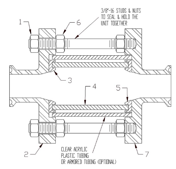
- (b) Unbolt the 3/8" hex nuts (1) and remove the top flange (2) on the sight glass. Disassemble the sight glass components by removing the top seal (3), glass tubing (4) and bottom seal (5). (Optional) Acrylic Plastic Tubing or Armored Tubing.
- (c) The interior of the flanges must be clean.
- (d) Place the new seal (5) with groove facing up into position on the bottom flange (7).
- (e) Carefully place the glass tubing (4) onto the bottom seal (5).
- (f) Place the new seal (3) with groove facing down on top of the glass tubing (4).
- (g) (Optional) Install Acrylic Plastic Tubing or Amrored Tubing
- (h) Place the top flange (2) back on top of unit.
- (i) Make sure the nuts (6) undereath the top flange (2) are threaded down and not restricting the seal of the top flange.
- (j) Then tighten down 3/8" hex nuts (1) across diameters to compress the seal uniformly to approx. 50 inch-lbs, which should be adequate for sealing the sight glass. Then tighten back the 3/8" hex nuts (6) undemeath the top flange.
- (k) The unit is now ready to be reinstalled into pipeline.
NOTE: After the unit has been heated and pressurized several times, the 3/3" hex nuts (1) should be checked for tightness.